TP-Link Deco X50-PoE Router User Guide
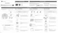

1. Set Up Your Deco
2. Power Up your Deco
Deco can be powered via a power adapter or a PSE device (such as a PoE switch) which complies with Power Source Class 2 (PS2) or Limited Power Source (LPS) and Electrical Energy
Source Class 1(ES1) of IEC 62368-1.
Please remain online (Wi-Fi or mobile data) for Step 1.
1. Download the Deco app from App Store or Google Play and log in with your TP-Link ID.
Mounting Guide
Option 1: Via PoE Switch (Compliant with 802.3at)
Option 2: Via Power Adapter
Note: If you don’t have an account, sign up first.
Connect an Ethernet cable from the
PoE switch (compliant with 802.3at) to
the Deco’s Ethernet port. The power
Plug one end of the provided power
adapter into the power port of the
Deco and the other end to a
Power Adapter
OR
Setup & Mounting Video
should not be less than 18 W.
standard electrical wall outlet.
PoE Switch (Compliant with 802.3at)
2. Follow the step-by-step instructions in the Deco app to set up your Deco.
©2023 TP-Link 7106510214 REV1.1.1
*Images may differ from actual products.
3. Mount Your Deco
Deco can be mounted to a wall, ceiling, or junction box, using the provided screws.
Choose an appropriate mounting method, then drill holes or mount directly with the
provided mounting bracket.
Option 1: On the Wall/Ceiling
The Deco can be mounted to the wall or the ceiling with the screws in the package.
Option 2: On a Wall Junction Box
The Deco can be mounted on a junction box. The junction box should be pre-installed with
a running-in-wall Ethernet cable. Ensure that the mounting holes align to your junction box.
Option 3: In a Ceiling Tile
The Deco can be installed in a ceiling tile with the screws in the package. Make sure the
ceiling tile is larger than the Deco.
*Here the standard US wall junction box is used as an example.
C-hole ×2:
For Single Gang Outlet Box (US)
Plastic Wall Anchors
Self-tapping Screws
Washers
Pan-head Screws
Wing Nuts
B-hole
C-hole
D-hole
D-hole
B-hole ×4:
For 3.5“ Round Junction Box (US)
×4
1
Remove the ceiling tile.
1
1
If your Ethernet cable feeds through the wall, position
the mounting bracket above the cable hole.
Detach the faceplate of the junction box with a
Phillips screwdriver.
Mark four positions for the screw holes and drill four 6
mm (15/64 in) diameter holes at the marked positions.
D-hole ×2:
For Single Gang Outlet Box (EU)
2
×4
Place the mounting bracket in the center of the
ceiling tile. Mark four positions for the screw holes
and a location for the Ethernet cable hole.
Drill four 4 mm (5/32 in) diameter holes for the
screws and a 25 mm (63/64 in) diameter hole for
the Ethernet cable at the marked positions.
2
2
Insert the plastic wall anchors into the 6 mm diameter
holes.
Feed the Ethernet cable through the mounting
bracket. Insert the enclosed screws and tighten them
with a Philips screwdriver to secure the mounting
bracket.
Drill Hole for Ethernet Cable
A-hole ×4:
For Ceiling/Wall Mount
Notes:
3
• Do not over tighten the screws.
• If the enclosed screws do not fit the junction box, use the
screws attached to the junction box instead.
Secure the mounting bracket to the ceiling tile
using four pan-head screws, washers, and wing
nuts.
3
Secure the mounting bracket to the wall by driving the
self-tapping screws into the anchors.
Make sure the mounting bracket lies flat against the
surface.
4
3
Tools You Might Need
Feed the Ethernet cable through the hole and set
the ceiling tile back into place.
Connect the Ethernet cable to the Ethernet port on
the Deco.
4
•
•
Phillips screwdriver
Connect the Ethernet cable to the Ethernet port on the
Deco.
Drill and drill bit (6 mm for wall mounting or 4 mm for ceiling tile
mounting)
5
•
•
(Optional) Drywall or keyhole saw (to cut a 25 mm diameter hole
for Ethernet cable feed)
4
Connect the Ethernet cable to the Ethernet port
on the Deco.
Orient the Deco LED according to the image, attach
the Deco to the mounting bracket, then rotate it
clockwise until it locks into place.
5
Orient the Deco LED according to the image,
attach the Deco to the mounting bracket, then
rotate it clockwise until it locks into place.
Cat5/6 UTP cable for indoor installations
Orient the Deco LED according to the image, attach
the Deco to the mounting bracket, then rotate it
clockwise until it locks into place.

| General | Details |
|---|---|
| Name | TP-Link Deco X50-PoE Router User Guide |
| Make | TP-Link |
| Language | English |
| Filetype | PDF (Download) |
| File size | 0.39 MB |

If you have any questions regarding TP-Link Deco X50-PoE Router User Guide, please ask here and describe the problem in detail.

TP-Link VR300 Archer Modem Router User Guide

TP-Link T150500-2-DT WiFi Router Instruction Manual

TP-Link Archer AX55 Wi-Fi 6 Router Installation Guide

TP-Link Omada ER8411 VPN Router Instructions

TP-Link Configure VDSL Router User Guide

TP-Link Archer BE805 BE19000 Tri-Band Wi-Fi 7 Router User Manual

TP-Link VR600 Wireless DSL Modem Router Installation Guide

TP-Link AX58 Dual Band Gigabit Wi-Fi 6 Router Installation Guide

TP-Link AC750 Wireless Dual Band Router Owner’s Manual

TP-Link AX6000 8-Stream Wi-Fi 6 Router Installation Guide


TP-Link Deco X50-DSL Whole Home Mesh WiFi 6 Router User Guide

Fiberhome Telecommunication Technologies Co Ltd SR1021F Wireless Router User Manual

Tenda AC1200 Wi-Fi Modem Router Instruction Manual
wildanet SDG 800 Series Broadband Router User Guide

DrayTek Vigor 1000B Multi WAN Load Balancing Router User Guide

ZTE MC888 Pro 5G CPE Router User Guide

Sagemcom Broadband FAST 5290 Fiber Wireless Router Installation Guide

BT Smart Hub 3 Broadband Router User Guide

D-Link G415 AX1500 4G Router User Guide

H3C Magic NX54 Gigabit Dual Band Wi-Fi 6 Wireless Router User Guide