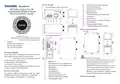
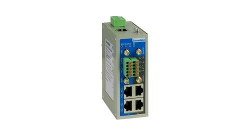
3onedata IRT5300L-5T2D-2P12_36 4G Wireless Router Installation Guide
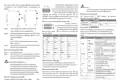

The product adopts 35mm standard DIN-Rail mounting which
is suitable for most industrial scenes, mounting steps as
follows:
terminal blocks, and supports P1 and P2
redundant power supply inputs. It could
connect to two external power supply inputs,
Notice:
If the SIM card needs to be changed, the device should
be power off first in case of damaging the card.
which can ensure the normal operation of the
device when one of the systems fails, thus
Antenna Connection
improving the reliability of network operation. The pin
definitions of power supply terminal blocks are shown in the
left figure, and the power supply input is 12~36VDC.
The device provides
2
WIFI antennas, the antenna
specifications are shown below:
Type
4G antenna
P/N
300504004
Gain (dBi) Quantity (pcs)
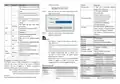
Serial Port and IO Ports Connection
3
2
This device provides 1
RS-232/485/422 serial port, 1 IO input
and output interface (reserved), and
2.4G wireless
8
-0.8
2
300504004
Checking LED Indicator
Step 1
Step 2
Check whether the DIN-Rail mounting kit that
comes with the device is installed firmly.
9
the interface type is 2x5-pin 3.81mm
pitch terminal blocks. The pin definitions of interface are
shown as follows:
The device provides LED indicators to monitor its operating
status, which has simplified the overall troubleshooting
process. The function of each LED is described in the table
below:
Insert the bottom of DIN-Rail mounting kit (one side
with spring support) into DIN-Rail, and then insert
the top into DIN-Rail.
PIN RS-232
RS-485
RS-422
T-
IO (Reserved)
LED
Indicate
ON
Description
The device is powered on or the
device is abnormal.
—
1
2
3
4
5
6
7
8
9
10
TX
DATA-
Tips:
—
RX
R-
—
GND
Insert a little to the bottom, lift upward and then
insert to the top.
—
DI-
DO-
GND
GND
Blinking
OFF
RUN
The device is running normally The
device is powered off or the device
is abnormal.
—
—
—
Check and confirm the product is firmly installed on
DIN-Rail, then mounting ends.
Step 3
—
—
DATA+
—
T+
—
—
ON
Wireless WiFi network is enabled
Wireless WiFi is in an active
network status
Disassembling DIN-Rail
—
R+
GND
—
GND
—
GND
Step 1
Power off the device.
Blinking
—
DI+
DO+
WLAN
Step 2
After lifting the device upward slightly, first shift out
the top of DIN-Rail mounting kit, and then shift out
the bottom of DIN-Rail, disassembling ends.
—
—
—
—
—
—
Wireless WiFi network is running
abnormally or turned off
Power supply P1/P2 is connected
and running normally
OFF
ON
Reset Button Setting
Notice Before Powering on:
This device provides 1 RESET button, press the button for
1-2s then release it to reboot the device; press the button for
5s then release it to restore factory defaults.
Power supply P1/P2 is
disconnected or running
abnormally
P1-P2
4G
Power ON operation: First insert the power supply
terminal block into the device power supply interface,
and then plug the power supply plug and power on.
Power OFF operation: First, remove the power plug,
then remove the wiring section of terminal block. Please
pay attention to the above operation sequence.
OFF
Mounting SIM Card
LTE module is operating normally
LTE module isn’t operating
All indicators are out. It means the
LTE signal of the opposite end is
weak or no signal.
Blinking
OFF
This device provides 2 SIM slots. It would pop up after you
insert a retrieve card pin in the little hole beside the SIM
slot, and then you should put the Micro SIM card in the slot
correctly and insert the slot back in the router.
Power Supply Connection
The device provides 4-pin 5.08mm power supply
input
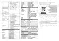
| General | Details |
|---|---|
| Name | 3onedata IRT5300L-5T2D-2P12_36 4G Wireless Router Installation Guide |
| Make | 3onedata |
| Language | English |
| Filetype | PDF (Download) |
| File size | 11.5 MB |

If you have any questions regarding 3onedata IRT5300L-5T2D-2P12_36 4G Wireless Router Installation Guide, please ask here and describe the problem in detail.

ARISTA AWE-5510 Wifi Router User Guide

MERCKU X6 Wi-Fi 6 Mesh Router User Manual

THREE CJB74V0HWAAC 4G Plus MiFi Mobile WiFi Router User Guide

Zbtlink AX1800 Wi-Fi 6 4G LTE Router User Manual

HiKOKI M12V2 Variable Speed Router Instruction Manual

D-Link DIR-615 Wireless Router User Manual

TP-Link E4 deco Router Installation Guide

hitron CHITA3.1 CHITA-RES Cable Modem Router User Guide

Roam-ON R10 MiFi 4G LTE WiFi Mobile Hotspot Router User Manual
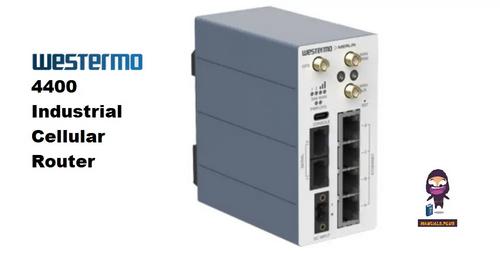
westermo 4400 Cellular Router User Guide