CISCO cBR Series Converged Broadband Router User Guide


What is a Cisco cBR Series Converged Broadband Router
Slot Numbering—Physical and Logical
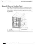
The Digital Midplane provides connectivity between various components in the chassis. It provides the
interconnect between the supervisors and all the interface slots. This interconnect includes differential pairs
used for ESI data plan links, Gigabit Ethernet/Ten Gigabit Ethernet control plane links, timing and single-ended
signals used for status and control functions. It also has connections for status and control of PICs, the power
shelf, and the fan modules.
RF Midplane
The RF midplane interconnects all RF-capable slots to allow backup RF line cards to send and receive RF
signals to and from an active RF line card PIC. It is designed to support a maximum of 24 RF ports on a PIC
with all ports carrying signals with frequency content up to 1.2 GHz. It supports downstream, upstream, and
a mixture of both.
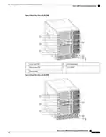
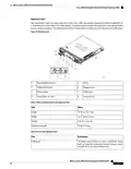
Rear Door (Optional)
The rear door provides protection to the PIC cables.
Lifting Handles
The Cisco cBR-8 chassis has four handles available for lifting. It is recommended to remove all circuit cards
before attempting to install the chassis in a rack, but at a minimum, the front Supervisors and line cards should
be removed before lifting the chassis with the available handles.
The accessory kit that ships with the chassis includes rack mount rails. These can be pre-assembled in the
rack to help slide the chassis into place. An optional front mounted lifting handle is also available to help with
chassis installation.
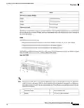
Rear Cable Connectivity
All permanent facility cabling is on the rear of the chassis. Connectors on the PICs provide connectivity to
the front mounted Supervisors and line cards.
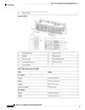
Front Side LED and Temporary I/O Locations
The LEDs are situated at the lower middle area on all the front mounted cards. Temporary I/O connectivity
ports are available on the left side of the Supervisor Card behind a removable door in the ejector handle.
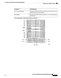
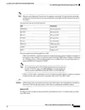
Slot Numbering—Physical and Logical
Table 2: Physical Slot Numbering on the Cisco cBR-8 Router
Component
Slot Numbering
Front and Rear Circuit Cards
Identified by a two number system. The numbers are separated by a
forward slash.
• The first number indicates the slot number (starting with 0 for
the first slot at the top).
• The second number indicates the side of the chassis. That is, 0
is for front-mounted cards and 1 is for rear-mounted cards.
However, on Cisco IOS-XE, the show platform command does
not show the second number 0 for front-mounted cards.
Supervisor Cards
Identified as SUP0 and SUP1.
What is a Cisco cBR Series Converged Broadband Router
8
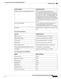
| General | Details |
|---|---|
| Name | CISCO cBR Series Converged Broadband Router User Guide |
| Make | Cisco |
| Language | English |
| Filetype | PDF (Download) |
| File size | 0.45 MB |

If you have any questions regarding CISCO cBR Series Converged Broadband Router User Guide, please ask here and describe the problem in detail.

Cisco Router RV345 / RV345P User Guide

Cisco RV160W Router User Guide

Cisco RV260W Router User Guide

Cisco RV260P Router User Guide

Cisco RV320 Small Gigabit Dual WAN VPN Router User Manual

CISCO RV320 Gigabit Dual WAN VPN Router User Guide

Cisco Router RV345/RV345P User Guide

Cisco RV160 Router User Guide

cisco RV340 Router User Guide


eero Pro 6E Mesh Router User Guide

Mercury Netcomm NF4V Fibre WiFi Gigabit Modem Router User Manual

COWMANAGER WIB2000 Coordinator Router User Manual

LAB4MUSIC Sipario Expanded Advanced MIDI Router User Manual

TP-Link Archer AX53 Gigabit Wi-Fi 6 Router User Guide

D-Link N300 4G Smart Router User Guide

UfiSpace S9501-28SMT Gateway Router Installation Guide

SDMC NE1611B WiFi Cable Modem Router User Manual

Tenda F9 Wireless Router Installation Guide

TP-Link AC1900 Archer AC1900 MU-MIMO Wi-Fi Router User Guide