CalAmp LMU-5541 Telematics Router Installation Guide


9/28/23, 4:30 PM
LMU-5541 Hardware & Installation Guide - PULS Wiki
4 LMU-5541™Connectors
The LMU-5541™ offers 22 connectors to access power, I/O, serial communications and other expansion capabilities. These connectors are:
SIM access
SIM Access Slot
Cellular main SMA
External GPS SMA (with tamper monitoring, 3.0v)
External WiFi SMA RP
2X Ethernet10/100 RJ45 USB Host Type A
USB On-The-Go (mini) Serial (RS232/485) DB-9
Serial 5 Pin Molex (switch power TTL Levels) Power, Ignition, I/O 4-Pin Molex
I/O connector 22-Pin Molex
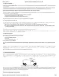
4.1 Power Connector
The LMU-5541™ uses a 4 pin Molex 43045-0402 connector as its power connection. The pin out is as follows:
Pin
1
Signal Name
VIN
Description
Power
5C888 Color
Red
Input or Output
Power / Input
Ground
2
GND
Ground
Black
3
4
ADC1
Analog to Digital Input 1
Green
White
Input
Input
INPUT 0
Input 0 / Ignition Sense – Digital Input
LMU-5541™ Header (looking into LMU)
6/29

| General | Details |
|---|---|
| Name | CalAmp LMU-5541 Telematics Router Installation Guide |
| Make | CalAmp |
| Language | English |
| Filetype | PDF (Download) |
| File size | 0.5 MB |

If you have any questions regarding CalAmp LMU-5541 Telematics Router Installation Guide, please ask here and describe the problem in detail.


LANCOM SYSTEMS 1790VAW GmbH Performance Router User Guide

TP-Link Archer MR600 Wireless 4G LTE Router Installation Guide

Mercury TD-W8960 Modem Router User Manual
SIERRA WIRELESS AirLink LX40 Enterprise LTE Router User Guide

ASUS GS-AX3000 Dual Band Gaming Router User Guide

NETGEAR RAX9 4-Stream WiFi 6 Router Owner’s Manual

Zbtlink WE2805-B 4G LTE Router User Guide

ZLWL ZR2720N Router User Guide

porodo PD-4GCPMF-BK 4G/LTE Home and Outdoor Portable Router Instruction Manual

ASUS RT-BE96U BE19000 Tri Band WiFi Router User Guide