CalAmp LMU-5541 Telematics Router Installation Guide


9/28/23, 4:30 PM
LMU-5541 Hardware & Installation Guide - PULS Wiki
4.2 I/O Connector
The LMU-5541™’s features expanded I/O capabilities via its 22-Pin Molex 43045-2202 connector. Its pin-out is as follows:
Pin
1
Signal Name
Input 1
Description
5C889 Color
Blue
Input or Output
Input
Input 1 – Digital Input
Input 2 – Digital Input
2
Input 2
Orange
Input
3
Input 3
Input 4
Input 3 – Digital Input
Input 4 – Digital Input
Input 5 – Digital Input
Input 6 – Digital Input
Input 7 – Digital Input
1 Bit Bus Data (T)
Violet
Gray
Input
Input
4
5
Input 5
Green & White
Blue & White
Black & White
Green & Black
Black
Input
6
Input 6
Input
7
Input 7
Input
8
1BB T Data
1BB GND
1 BB R Data
1 BB Gnd
Output 0
Output 1
Output 2
Output 3
Output 4
Output 5 - LED
Output 6 - LED
ADC 2
Input/Output
Ground
Input/Output
Output
Output
Output
Output
Output
Output
Output
Output
Input
9
1 Bit Bus Ground
10
11
12
13
14
15
16
17
18
19
20
21
22
1 Bit Bus Data (R)
Orange & Black
Black
1 Bit Bus Ground
Output 0 - Starter Disable Relay Driver
Output 1 - Digital Output
Output 2 - Digital Output
Output 3 - Digital Output
Output 4 - Digital Output
Output 5 - LED 1 Driver
Output 6 - LED 2 Driver
Analog to Digital Input 2
Analog to Digital Input 3
Analog to Digital Input 4
Analog to Digital Input 5
Green
Brown
Yellow
Blue & Orange
Green & Black & Orange
Red & Green
Orange & Green
Black & Red
White & Red
Orange & Red
Blue & Red
ADC 3
Input
ADC 4
Input
ADC 5
Input
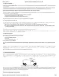
LMU-5541™ Header (looking into LMU)
4.3 Serial Interface Connectors
The LMU-5541™ offers 2 serial interface connections (Host/Aux1 and DB-9 SerialAux 2) on its front face. Host/AUX1 is provided via a Molex 43650-0501 connector
using the following pin out:
Pin
Signal Name
Description
134364-SER Color
Input or Output
1
VIN_FILT
Filtered LMU Power
Red
Power Supply
2
3
4
5
VCC3V3
Ground
TX
3.3V Power
Ground
Orange
Black
Blue
Power Supply
Ground
Transmit Data
Receive Data
Input to LMU
Output From LMU
RX
Green
Serial Interface Connector
Users should only use CalAmp approved serial adapters for these connections.
4.4 Serial Interface Cables & Accessories
Serial Connectivity is a one cable solution. You can use either part numbers 134364-SER or 134364-MDT.
LMU Serial Cable (Part Number 134364-SER)
7/29

| General | Details |
|---|---|
| Name | CalAmp LMU-5541 Telematics Router Installation Guide |
| Make | CalAmp |
| Language | English |
| Filetype | PDF (Download) |
| File size | 0.5 MB |

If you have any questions regarding CalAmp LMU-5541 Telematics Router Installation Guide, please ask here and describe the problem in detail.


TP-Link Archer GE650, GE550 Wi-Fi 7 Gaming Router User Guide

GL iNet GL-B3000/Marbel AX3000 Wireless Router User Manual

wis network 5G CPE Pro -Home Router User Guide

cradlepoint S5A037A Enterprise Branch Router User Manual

NETGEAR RAX5 Model AX1600 WiFi 6 Router User Guide

TechPowerUp Openwrt ONE Wi-Fi 6 Router User Manual

cradlepoint E110 Enterprise Branch Router User Manual

MSA Safety FS-ROUTER-BAC2 FieldServer BACnet Router Instructions

MILLITRONIC MG360 Wireless WiGig Router User Manual

perle IRG5410 Router User Guide