ELTEC CYBOX RT 2-A Wireless Automotive Router Installation Guide


CYBOX RT 2-A
3
HARDWARE
3.1
DEVICE CONNECTORS
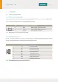
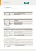
3.1.1 POWER SUPPLY CONNECTORS
The electrical power can be supplied to the device using the MSTB 2.5/ 3 GF power connector, labeled PWR.
Table 1 shows the pin assignment of the power supply connector.
PIN
1
SIGNAL NAME
+VIN
DESCRIPTION
Supply voltage, positive terminal
Supply voltage, negative terminal
Ignition (power on) signal
2
-VIN
3
Ignition
Table 1 Pin Assignment of Power Supply Connector (PWR)
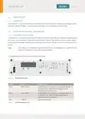
3.1.2 ETHERNET INTERFACES
The LAN ports of the CyBox RT 2-A are utilizing RJ45 connectors with the pin assignment as shown in Table
2 below. Mating connectors are available from several manufacturers.
PIN
1
SIGNAL NAME
DESCRIPTION
D1+
D1-
D2+
D3+
D3-
D2-
D4+
D4-
First data line plus
First data line minus
Second data line plus
Third data line plus
Third data line minus
Second data line minus
Fourth data line plus
Fourth data line minus
2
3
4
5
6
7
8
Table 2 Pin Assignment of RJ45 Ethernet Connectors (LAN 1..5)
3
| General | Details |
|---|---|
| Name | ELTEC CYBOX RT 2-A Wireless Automotive Router Installation Guide |
| Make | ELTEC |
| Language | English |
| Filetype | PDF (Download) |
| File size | 0.29 MB |

If you have any questions regarding ELTEC CYBOX RT 2-A Wireless Automotive Router Installation Guide, please ask here and describe the problem in detail.

ELTEC CYBOX RT 2-A Automotive Wireless Router Instructions


atop Technologies AWR5805, AWR5805P Wireless Router Installation Guide

Tenda AC19 Dual Band Gigabit WiFi Router Installation Guide

Linksys WRT300N Wireless-N Broadband Router User Guide

Cudy WR3000S AX3000 Gigabit Mesh WiFi 6 Router Installation Guide

Adtran SDG-8610 Service Delivery Gateway WiFi 6 Gigabit Router Instruction Manual

GL iNet GL-A1300 AC1300 Gigabit Wireless Router User Guide

TP-Link EC223-G5 Aginet AC1200 MU-MIMO Wi-Fi Router User Manual

ASUS RT-BE96U BE19000 Tri Band WiFi Router User Guide

TELTONIKA Networks RUT956 4G LTE Router User Guide

Juniper NETWORKS ACX Series Paragon Automation Router User Guide