ELTEC CYBOX RT 2-A Wireless Automotive Router Installation Guide


CYBOX RT 2-A
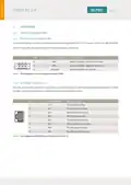
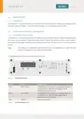
3.3.2 BACK PANEL DISTRIBUTION
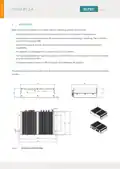
The figure below provides an overview of the back panel.
Figure 4
Back Panel Overview
CONNECTOR
Earthing Bolt
FUNCTION
Shield
DESCRIPTION
The earthing bolt can be found on the lower left side
of the front panel
PWR
System power
Triple speed Gigabit Ethernet ports
Fakra antenna connectors
LAN 1-5
LTE 1-2
WLAN 1-2
GNSS
1 Gb Ethernet
Antenna connectors
Antenna connectors
Antenna connector
CAN interface
Fakra antenna connectors
Fakra antenna connector
CAN
1 x Min-D 9 pos. female, 1 x Min-D 9 pos. male
Table 5
Back Panel Description
3.3.3 ASSIGNMENT FRONT PANEL LABELLING – SOFTWARE
•
•
•
•
•
The ports and LEDs “LAN 1” to “LAN 5” correspond respectively to the interfaces “eth0” to “eth4”
The LEDs “WLAN 1” / “WLAN 2” and “LTE 1” / “LTE 2” refer to WLAN and LTE modules
WLAN modules are called “radio” within the software
LTE modules are called “modem” within the software
The purpose of the antennas depends on the modules inserted in your CyBox model
6
| General | Details |
|---|---|
| Name | ELTEC CYBOX RT 2-A Wireless Automotive Router Installation Guide |
| Make | ELTEC |
| Language | English |
| Filetype | PDF (Download) |
| File size | 0.29 MB |

If you have any questions regarding ELTEC CYBOX RT 2-A Wireless Automotive Router Installation Guide, please ask here and describe the problem in detail.

ELTEC CYBOX RT 2-A Automotive Wireless Router Instructions


TP-Link Archer C86 MU-MIMO Wi-Fi Router Installation Guide

JUniPer MX304 Universal Router User Guide

LTC 1221 4G Wireless Router Installation Guide

xiaomi BE3600-2.5G Router User Manual

xunison Hub M50 Mesh Tower High Performance Router User Guide

TP-Link Archer C20 Wireless Dual Band Router Installation Guide

BUFFALO WZR2-G300N Wireless Router User Guide

JUNIPER SSR1400 Session Router User Guide

Cudy WR3000E AX3000 Gigabit Mesh Wi-Fi 6 Router Owner’s Manual

TP-Link TL-WR1502X AX1500 WiFi 6 Travel Router Installation Guide