ELTEC CYBOX RT 2-A Wireless Automotive Router Installation Guide


CYBOX RT 2-A
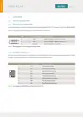
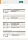
3.1.3 CAN INTERFACES
The CAN interfaces of the CyBox RT 2-A are utilizing D-Sub 9 connectors. Two CAN connectors are available
(in and out) to connect one CAN device only. Both CAN connectors provide the same CAN signals so that a
Mating connectors are available from several manufacturers.
PIN
1
SIGNAL NAME DESCRIPTION
NC
Not connected
Data –
2
CAN–
GND
NC
3
Signal ground
Not connected
Not connected
Not connected
Data +
4
5
NC
6
NC
7
CAN+
NC
8
Not connected
9
NC
Not connected
Table 3 Pin Assignment of CAN Connectors
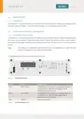
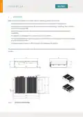
3.1.4 ANTENNA CONNECTORS
The FAKRA antenna connectors are located at the backside of the device. All connectors are labeled for
each radio interface and GNSS.
When connecting an antenna to the FAKRA connector, make sure that you hear a ‘click’ sound confirming
proper mounting. To remove an antenna, the upper middle part of the connector has to be gently pushed
down with one finger and pulled away from the panel as illustrated below.
FAKRA CONNECTORS
4
| General | Details |
|---|---|
| Name | ELTEC CYBOX RT 2-A Wireless Automotive Router Installation Guide |
| Make | ELTEC |
| Language | English |
| Filetype | PDF (Download) |
| File size | 0.29 MB |
 (1 votes, average: 5.00 out of 5)
If you have any questions regarding ELTEC CYBOX RT 2-A Wireless Automotive Router Installation Guide, please ask here and describe the problem in detail.

ELTEC CYBOX RT 2-A Automotive Wireless Router Instructions


Keep Your Home IP MA-B256 Router Owner’s Manual

xiaomi CB0401 5G CPE Pro Router Instructions

Trueview T18168-AE Wireless Router 4G 5G Mobile Sim Based Router User Guide

D-Link EXO AX AX1800 Wi-Fi Router User Guide

acer 952483 WAVE 7 Wi-Fi Mesh Router User Guide

BUFFALO WZR2-G300N Wireless Router User Guide

ASUS RT-BE92U Tri Band WiFi 7 Router User Guide

TRUPER ROU-A3 Professional Router User Manual

TP-Link AX1800 Wi-Fi 6 Gigabit Dual Band Wireless Router User Guide

TP-Link HB611-SGST Singtel WiFi 7 Router User Guide