mafell LO 55 Hand Router Instruction Manual


- When operating the machine outdoors, use of an - Only use milling cutters approved for manual feed.
earth-leakage circuit-breaker is recommended.
- Only use sharp and undamaged milling cutters. You
will achieve improved surfaces and reduce the
danger of backlash.
- Do not work on workpieces that are too small or too
large for the capability of the machine.
- Damaged cables or plugs must be immediately
replaced. Replacement may only be carried out by
Mafell or an authorised MAFELL service workshop
in order to avoid safety hazards.
- Avoid sharp bends in the cable. Especially when
transporting and storing the machine, do not wind
the cable around the machine.
- Only use milling cutters approved for manual feed.
- Only begin milling the workpiece when the milling
- Only hold the power tool by the isolated handles, as
the milling cutter could encounter and cut into its
own connecting cable. The milling cutter contacting
a "live" wire may render exposed metal parts of the
tool "live" and could cause the operator to suffer an
electric shock.
cutter has achieved its full speed.
- Use clamps or another practical way to secure and
support the workpiece to a stable support. Holding
the workpiece only with your hand or against your
body leaves it unstable and may lead to loss of
control.
- Only put down the machine after switching off once
the milling tool has come to a standstill.
Do not use:
- Cracked and misshapen milling cutters.
- Blunt milling cutters as they impose an excessive - Only begin milling the workpiece when the milling
load on the motor. cutter has achieved its full speed.
- Milling cutters that are not suitable for the milling - Always lead the connecting cable away from the
idling speed.
machine to the rear while milling.
- An even feed during milling increases the life time
of milling cutter and machine and achieves a clean
milling pattern. Always mill in counter direction when
machining edges.
- Only put down the machine after switching off once
the milling cutter has come to a standstill or unscrew
the clamping for the automatic reverse stroke on the
machine. The machine is locked by releasing the
column clamping lever 18 (Fig. 2).
Instructions on the use of personal protective
equipment:
- The noise pressure level at the ear generally
exceeds 85 dB(A). Therefore wear ear protectors
during work.
- Wear protective goggles during work.
- Wear a dust protection mask to prevent health
damage.
- Milling cutters must be replaced in good time, as
blunt milling cutters do not only increase the danger
of backlash, but also place an unnecessary strain
on the motor. The milling cutters must be clamped
in accordance with chapter 5.3.
- The wood dust arising during milling impairs the
necessary view and is partly injurious to health. If
the machine is used for longer periods, it must
therefore be connected to a chip extractor, e.g. a
portable small extractor, if the work is not carried out
outdoors or in a sufficiently ventilated room. The air
velocity must be at least 20 m/s.
Instructions on operation:
- Never reach into the working range of the milling
cutter or underneath the base plate while the
machine is running (danger of injury)!
- Firmly hold onto the machine with both hands at the
handles provided already before switching it on.
- Provide a free and non-slip location with adequate
lighting.
- The power plug must be pulled before replacing
tools, making adjustments and repairing
malfunctions (this also includes removing jammed
chips).
- Examine the workpiece for foreign objects. Do not
mill into metal parts, e.g. nails (danger of backlash).
- Before starting up, check the tight seat of the milling
cutter and its correct running.
-24-

Instructions on service and maintenance:
5.2 Chip and dust extraction
- Regularly cleaning the machine, especially the Chips arising during milling as well as hazardous dusts
adjusting devices and guides, constitutes an arising from certain materials can be extracted by
important safety factor.
- Only original MAFELL spare parts and accessories
means of a commercial vacuum cleaner or with an
external dust extractor.
may be used. Otherwise the manufacturer will not To do so, attach the hose end of the vacuum cleaner
accept any warranty claims and cannot be held to the hose connector 11 (see Fig. 2) of the base plate.
liable.
For improved extraction, an additional extraction
adapter can be used (included in the scope of supply).
When working with a guide rail, an extraction adapter
with height compensation (included in the scope of
supply) is used.
When machining edges, a chip deflector which guides
any arising chips away from the operator and improves
extraction can be additionally mounted. The chip
deflector is included in the scope of supply.
4
Layout
4.1 Depicted components
(see Fig. 1 and 2)
(1)
Depth stop
(2)
Handle depth stop
Scale for the depth stop
Optical fibre speed adjustment
Speed push button
Speed reduction button
Power-on lock
(3)
5.3 Clamping of milling cutters
(4)
The machine is as a standard equipped with a
precision collect Ø 8 mm. It is possible to fasten milling
cutters with corresponding shaft diameter in this collet.
(5)
(6)
(7)
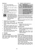
Danger
(8)
Handle
It is imperative to pull the mains
plug before replacing the milling
cutter. Place the machine on its
head or put it down on its side. Do
not set the machine down on the
side with the hose connector! This
can result in damage to the
workpiece.
(9)
Connecting cable
Switch trigger
(10)
(11)
(12)
(13)
Hose connector
Wing screw for support foot
Wing screw to fasten parallel guide
fence, extraction adapter, chip
deflector and template guides
Clamping
(14)
(15)
(16)
(17)
(18)
(19)
Base plate
•
•
•
•
Set the machine to the topmost position by
actuating the column clamping lever 18 (Fig. 2).
Revolving depth stop with grub screws
Fine adjustment depth stop
Cam lever
Open the tool clamping lever 20 (Fig. 3)
completely downwards.
Place the machine on its head or put it down on
its side.
Column clamping lever
Handle
Push the clean milling cutter shaft into the open
collet up to the minimum clamping depth
marking. If there is no marking for the minimum
clamping depth, push at least three third of the
shaft length of the milling cutter shaft into the
open collet.
5
Setting / adjustment
5.1 Mains connection
Prior to commissioning make sure that the mains
voltage complies with the operating voltage stated on
the machine's rating plate.
-25-
| General | Details |
|---|---|
| Name | mafell LO 55 Hand Router Instruction Manual |
| Make | mafell |
| Language | English |
| Filetype | PDF (Download) |
| File size | 2.24 MB |

If you have any questions regarding mafell LO 55 Hand Router Instruction Manual, please ask here and describe the problem in detail.

mafell LO65EC Wood Carving Hand Router Instruction Manual


MERCUSYS MR62X Wireless Router Installation Guide

caravansplus RV WI-FI Dishydock Router User Guide

TELTONIKA RUT260 LTE Router User Manual

D-Link R95 BE9500 Wi-Fi 7 Router User Guide

NETGEAR NIGHTHAWK RS Series Dual Band Wi-Fi 7 Router Instruction Manual

Actiontec WF-815 Tri-Band Wi-Fi6E Router Owner’s Manual

CHIMA SAX3000 EasyMesh WiFi 6 Router Owner’s Manual

cradlepoint E110 Enterprise Branch Router User Manual

SMAWAVE SRE410 LTE CPE Router User Guide

Tenda AC9 AC1200 Dual Band Gigabit WiFi Router Installation Guide