Home > LANCOM SYSTEMS > LANCOM SYSTEMS 1930EF Gigabit Ethernet Black Wired Router User Guide
LANCOM SYSTEMS 1930EF Gigabit Ethernet Black Wired Router User Guide
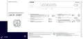

Mounting & connecting
➀
➁
➂
➃
➄
Hardware Quick Reference
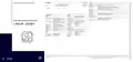
WAN 1 interfaces (SFP / TP combo port)
Configuration interface
➀
➃
➄
Insert a suitable SFP module (e.g. 1000Base-SX or 1000Base-LX) into the
SFP port. Choose a cable compatible with the SFP module and connect
it as described in the module’s documentation. SFP module and cable are
not included.
If desired, alternatively connect the WAN 1 TP interface to a WAN modem
using the provided Ethernet cable with green connectors.
Use the included serial configuration cable to connect the serial
interface (COM) to the serial interface of the device you want to use
for configuring / monitoring.
LANCOM 1930EF
USB interface
You can use the USB interface to connect a USB printer or a USB
storage device.
WAN 2 interface (TP)
Connect the WAN 2 interface to a WAN modem using the provided
Ethernet cable with green connectors.
➁
➂
Power connector and grounding point (device back side)
Supply power to the device via the power connector. Please use the
IEC power cable supplied (separately available for WW devices).
➅
➆
➅
➆
Warning! High touch current.
Connect to earth before
connecting the power supply.
Ethernet interface
Use the cable with the kiwi-colored connectors to connect one of the
interfaces ETH 1 to ETH 4 to your PC or a LAN switch.
ATTENTION: High touch current possible! Connect to earth before
connecting the power supply.
Before initial startup, please make sure to take notice of the information regarding the intended use in the enclosed
installation guide!
Please observe the following when setting up the device
→ For devices to be operated on the desktop, please attach the adhesive rubber footpads
→ Do not rest any objects on top of the device and do not stack multiple devices
→ Keep all ventilation slots of the device clear of obstruction
→ Mount the device into a 19” unit in a server cabinet using the provided screws and mounting brackets. Pay
attention to the “R” and “L” marks on the brackets for accurate mounting.
i
Operate the device only with a professionally installed power supply at a nearby power socket that is freely
accessible at all times.
The power plug of the device must be freely accessible.
Please note that support for third-party accessories is not provided.

| General | Details |
|---|---|
| Name | LANCOM SYSTEMS 1930EF Gigabit Ethernet Black Wired Router User Guide |
| Make | LANCOM SYSTEMS |
| Language | English |
| Filetype | PDF (Download) |
| File size | 0.14 MB |


LANCOM SYSTEMS 1800EF-4G High Availability Networking Via Fiber Router Owner’s Manual

LANCOM SYSTEMS 1790-4G+ High-Performance VPN Router Installation Guide

LANCOM SYSTEMS 1790VAW GmbH Performance Router User Guide

LANCOM SYSTEMS 1800EFW-5G Router Installation Guide

LANCOM SYSTEMS LANCOM OAP-830 Wireless Router User Guide

LANCOM SYSTEMS LANCOM 1790-4G Plus High-Performance VPN Router Instruction Manual

LANCOM SYSTEMS VPN 1900EF Router Instruction Manual

LANCOM Systems 1780EW-4G+ High Performance Mobile VPN Router User Guide

LANCOM Systems 1793VA VDSL Voip VPN Router User Guide

LANCOM SYSTEMS IAP-4G Plus LTE 4G Router User Guide

LANCOM SYSTEMS 1930EF Gigabit Ethernet Black Wired Router User Guide Overview
Summary of Contents
- Page 1: Mounting & connecting Insert a suitable SFP module (e.g. 1000Base-SX or 1000Base-LX) into the SFP port. Choose a cable compatible with the SFP module and connect it as described in the module’s documentation. SFP module and cable are not included. If desired, alternatively connect the WAN 1 TP interface to a WAN modem using the provided Ethernet cable with green connectors. Use the included serial configuration cable to connect the serial interface (COM) to the serial interface of the device you want to use for configuring/monitoring. Connect the WAN 2 interface to a WAN modem using the provided Ethernet cable with green connectors. Supply power to the device via the power connector. Please use the IEC power cable supplied. Warning! High touch current. Connect to earth before connecting the power supply. Before initial startup, please make sure to take notice of the information regarding the intended use in the enclosed installation guide. Please observe the following when setting up the device: For devices to be operated on the desktop, please attach the adhesive rubber footpads. Do not rest any objects on top of the device and do not stack multiple devices. Keep all ventilation slots of the device clear of obstruction. Mount the device into a 19” unit in a server cabinet using the provided screws and mounting brackets. Pay attention to the “R” and “L” marks on the brackets for accurate mounting.
- Page 2: LED description & technical details Internal power supply unit (100–240 V, 50-60 Hz) Max. 18 W Temperature range 0–40 °C, humidity 0–95 %; non-condensing Robust metal housing, 1 HU with mounting brackets for 19“ installation 1 Ethernet cable, 3 m (kiwi colored connectors) 1 IEC power cord 230 V (not for WW devices) Two 19” brackets for rack mounting Reset button: short press > Restart the device; long press > Reset the device Detailed interface specifications can be found in the device data sheet after entering the device name at www.lancom-systems.com/downloads. Device operational, resp. device paired / claimed and LANCOM Management Cloud (LMC) accessible No password set. Without a password the configuration data in the device is unprotected. Connection to the LMC active, pairing OK, device not claimed.

NETGEAR RS600 Tri Band WiFi 7 Router User Guide

KEENETIC Hero KN-1012 Mesh Wi-Fi 6 Multi-Gigabit Router User Guide

NETGEAR MR6450 Nighthawk M6 5G Wi-Fi 6 Mobile Router User Guide

JUNIPER SSR1300 Session Smart Router User Guide

ASUS ROG STRIX GS-AX3000 Dual-Band Gaming Router User Guide

Spectrum IP6442B WiFi 6E Router User Manual

MALMBERGS 2700490DK 4G Network Router Instruction Manual

D-Link DSR-250V2 Unified Services Router Installation Guide

ZTE U30 Air 5g Portable WiFi Mobile WiFi Router User Guide

NetComm NTC-500 5G IoT Router Instructions