Home > UBIQUITI NETWORKS > UBIQUITI NETWORKS 2.4GHz Air Router User Guide
UBIQUITI NETWORKS 2.4GHz Air Router User Guide


AirRouter User Guide
Chapter 3: AirOS™
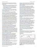
Firewall entries can be specified by using the following
criteria:
• The wireless interface and all of the connected wireless
clients are considered part of the external network
and all network devices on the LAN side as well as the
Ethernet interface itself are considered as part of the
internal network when the AirRouter is operating in
Station or Station WDS mode.
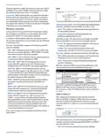
Interface The interface (WLAN or LAN) where filtering of
the incoming/passing-through packets are processed.
IP Type Sets which particular L3 protocol type (IP, ICMP,
TCP, UDP) should be filtered.
Wireless/wired clients are routed from the internal
network to the external one by default. Network Address
Translation (NAT) functionality works the same way.
Source IP/Mask The source IP of the packet (specified
within the packet header), usually it is the IP of the host
system which sends the packets.
Src Port The source port of the TCP/UDP packet (specified
within the packet header), usually it is the port of the host
system application which sends the packets.
Destination IP/Mask The destination IP of the packet
(specified within the packet header), usually it is the IP of
the system which the packet is addressed to.
Dst Port The destination port of the TCP/UDP packet
(specified within the packet header), usually it is the
port of the host system application which the packet is
addressed to.
Comment Field used to enter a brief description of the
firewall entry.
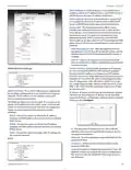
WLAN Network settings
On Enables or disables the effect of the particular firewall
entry. All added firewall entries are saved in system
configuration file, however only the enabled firewall
entries will be active on the AirRouter.
IP Address This is the IP address to be represented by
the WLAN interface which is connected to the internal
network according to the wireless operation mode
described above. This IP will be used for the routing of
the internal network (it will be the Gateway IP for all
the devices connected on the internal network). This IP
address can be used to access the management interface
of the AirRouter.
Not Can be used for inverting the Source IP/mask, Source
Port, Destination IP/mask and Destination Port filtering
criteria (i.e. if not is enabled for the specified Destination
Port value 443, the filtering criteria will be applied to all
the packets sent to any Destination Port except the 443
which is commonly used by HTTPS).
Netmask This is used to define the device IP classification
for the chosen IP address range. 255.255.255.0 is a typical
netmask value for Class C networks, which support IP
address range 192.0.0.x to 223.255.255.x. Class C network
Netmask uses 24 bits to identify the network (alternative
notation “/24”) and 8 bits to identity the host.
Click Save to save your firewall entries or click Cancel to
discard your changes.
All active firewall entries are stored in the FIREWALL chain
of the ebtables filter table, while the device is operating
in Bridge mode. Please refer to the ebtables manual for a
detailed description of the firewall functionality in Bridge
mode.
Enable NAT Network Address Translation (NAT) enables
packets to be sent from the wired network (LAN) to the
wireless interface IP address and then sub-routed to other
client devices residing on the local network while the
AirRouter is operating in Access Point or Access Point WDS
mode and in the reverse direction in Station and Station
WDS mode.
Click Change to save the changes made in the Network
tab.
Router
The role of the LAN and WLAN interface will change
depending on the Wireless Mode selected while the
AirRouter is operating in Router mode:
Enable NAT Protocol While NAT is enabled, data packets
could be modified in order to allow pass-through to the
Router. To avoid packet modification of some specific
packets, like: SIP, PPTP, FTP, RTSP; uncheck the respective
checkbox.
• The wireless interface and all connected wireless clients
are considered as part of the internal LAN and the
Ethernet interface is dedicated for the connection to
the external network while the AirRouter is operating in
Access Point or Access Point WDS mode.
NAT is implemented using the masquerade type firewall
rules. NAT firewall entries are stored in the iptables nat
table, while the device is operating in Router mode. Please
refer to the iptables tutorial for detailed description of the
NAT functionality in Router mode.
Ubiquiti Networks, Inc.
15
| General | Details |
|---|---|
| Name | UBIQUITI NETWORKS 2.4GHz Air Router User Guide |
| Make | UBIQUITI NETWORKS |
| Language | English |
| Filetype | PDF (Download) |
| File size | 5.15 MB |

If you have any questions regarding UBIQUITI NETWORKS 2.4GHz Air Router User Guide, please ask here and describe the problem in detail.

UBIQUITI NETWORKS ER-12 10 Port Gigabit Router User Guide


Cudy LT15E 4G Cat 12 AX3000 Wi-Fi 6 Router Installation Guide

NETGEAR MR6450 Nighthawk M6 5G Wi-Fi 6 Mobile Router User Guide

inseego 5G FG2000 Router User Guide

TP-Link Aginet EX1110 AXE11000 Tri-Band 10G WiFi 6E Router Installation Guide

LANCOM SYSTEMS 1800EF-4G High Availability Networking Via Fiber Router Owner’s Manual

acer 952483 WAVE 7 Wi-Fi Mesh Router User Guide

MERCKU X6 Wi-Fi 6 Mesh Dual WAN Router Installation Guide
UniFi A3000 WiFi 6 Router User Manual

LINKSYS FGW5500 5G WiFi 6 Router User Guide

BEC 7000 R26-W Gigabit LTE Outdoor Router with Hotspot User Guide